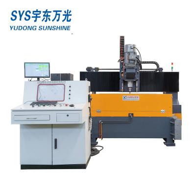
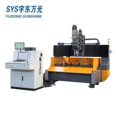
High Speed Plate Drilling Milling Machine model PMZ2016H
Application: The platform on which the workpiece works. The workpiece is placed on the base support bar and clamped by the clamp cylinder to fix the workpiece.
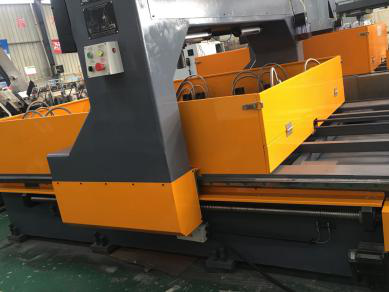
The bed is made of square tube welding, and the precision is stable after tempering heat treatment to remove stress.The two sides of the bed are parallel with two linear guides, and one side is equipped with a high precision ball screw.The sliding blocks on both sides of the guide rail are equipped with movable numerical control sliding platforms.The longitudinal movement of the CNC sliding table is driven by a servo motor.
The gantry adopts square tube welded structure, and the stress is removed by tempering heat treatment.The two legs are mounted on the numerical control sliding table of the bed body respectively, and move longitudinally along with the numerical control sliding table.The front of the cross beam is provided with two linear guide rails, and a precision ball screw is provided above the cross beam.The ball screw is equipped with a CNC sliding plate that can move laterally.The CNC slide is driven by the servo motor to realize the transverse movement of the ball screw

2.1 Mechanical parts
| No. | Item | PMZ2016 |
| 1 | Size of machine(mm) | 5000x2700x2800mm |
| 2 | Number of machine bed frame | 1 Set |
| 3 | Number of Gantry frame | 1 Set |
| 4 | Number of Spindle heads | 1 Set |
| 5 | Air-actuated control System | 1 Set |
| 6 | Hydraulic control System | 1 Set |
| 7 | Automatic Chip removal | 1 Set |
| 8 | Circulation Cooling system | 1 Set |
| 9 | Electrical System | 1 Set |
| 10 | The part responsible by purchaser | Embedded plates and anchor bolts required for the cement foundation and equipment of the installation site shall be prepared according to the foundation drawing provided by the supplier |
2.2 Electric control unit
| 1 | CNC system | PLC control system |
| 2 | Driving system | Panasonic servo motor |
3. Plat Drilling Machine Main Parameters
| Item | Model | Unit | PMZ2016 |
| Max working size | Length x width | mm | 2000×1600 1 Pcs |
| 1000×1600 2 Pcs | |||
| 1000x800 4 Pcs | |||
| Overlay thickness | mm | 100 | |
| Drilling spindle | Number of spindle | piece | 1 |
| Model of spindle | Morse 4 # cone hole | ||
| Speed of spindle | r/min | 120-560 Stepless speed inverter | |
| Feeding type | Hydraulic self-controlled stroke drilling spindle head | ||
| Feeding travel | mm | 180 | |
| Drilling diameter | mm | Φ12-Φ60 | |
| Main motor power | KW | 5.5 | |
| Workpiece hydraulic clamping | Number of clamping cylinder | Pcs | 12 |
| Clamping power/piece | KN | 7.5 | |
| Clamping way | Foot switch control | ||
| Hydraulic pump pressure | MPa | 6 | |
| Hydraulic oil tank volume | L | 100 | |
| Electric control | Control type | PLC+IPC | |
| X axis servo motor | KW | 1.5 | |
| Y axis servo motor | KW | 1.5 | |
| Motor power of hydraulic pump | KW | 2.2 | |
| Drilling precision | Drilling precision | mm | ±0.5mm |
| Re-positioning precision | mm | ±0.1mm | |
| Cooling type | Forced circulating water cooling | ||
| Chip removal method | Flat chain automatic chip conveyor | ||
| Machine size | LxWxH | mm | 5000x2650x2800 |
| Machine weight(appx) | T | 6 | |
4. Machine working environment
| 1 | Power | three-phase and four-wire system |
| 2 | Voltage | 415V±10% |
| 3 | Frequency | 50Hz |
| 4 | Working Temperature | 0℃-40℃ |
| 5 | Relative humidity | <90% non-condensing |
| 6 | Compressed air | Voltage:0.4MPa |
5. Introduction of each component of machine
The machine is mainly composed of drilling host unit, table moving unit, clamp assembly, pneumatic system, electrical system, hydraulic system, etc.
 English
 Русский
 Español
 العربية


