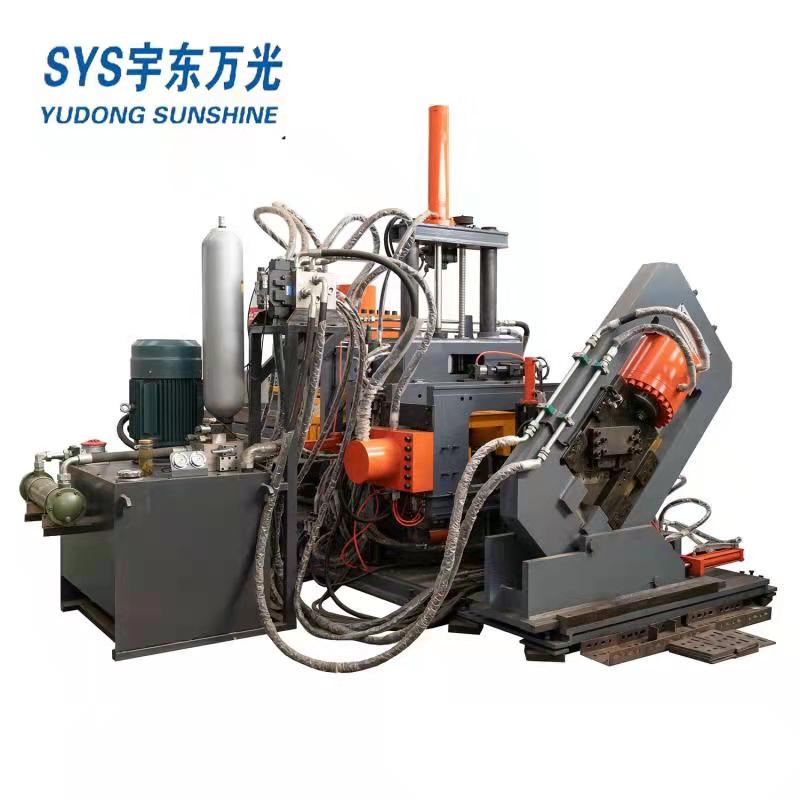
Cnc Channel Punching and Cutting Machine
The electrical control system of this machine is advanced and reasonable, the workpiece programming is easy to learn, and the operation is simple.
Configure the upper computer, and install special automatic programming and system control software, complete the connection of the servo motor, to ensure fast, accurate positioning and maintenance free.The control software can conveniently and flexibly manage the contents of the workpiece library and display the workpiece graphics in real time on the screen.The control software can realize automatic relocation function.The control software monitors the operation of the machine at any time. When a fault occurs, the CRT will display the detailed fault cause and treatment method.

1. Hydraulic power part
The machine adopts independent hydraulic station, easy to maintain the equipment, all the pipe joints adopt sleeve type connection, fundamentally avoid joint leakage, hydraulic valve adopts valve block connection, at the same time using plate valve and cartridge valve, reduce the pipeline connection, the hydraulic system is tighter.Line losses are minimized.System efficiency has been fully brought into play.
2. Main technical parameters of the equipment
| No. | Item | unit | specification | |
| 1 | Channel size | 8#-18# | ||
| Angle size | mm | L63X4-L140X10 | ||
| Flat bar size | mm | 60X5-180X10 | ||
| 2 | Raw material length | mm | 9000 | |
| 3 | Max. Punching diameter | mm | φ26 (web slot hole 22X60, flange slot hole) | |
| 4 | Punching force | KN | 1000 | |
| 5 | Cutting force | KN | 1500 | |
| 6 | Punching sides | side | 3 | |
| 7 | Punching head quantity of each side | piece | 4+2+2 | |
| 8 | Row of each punching side | row | arbitrarily | |
| 9 | Cnc axis | No. | 3 | |
| 10 | Min. End cutting length | mm | 50 | |
| 11 | Hydrualic force | Mpa | 25 | |
| 12 | Hydraulic cooling way | Water cooling | ||
| 13 | Pneumatic system pressure | Mpa | 0.8 | |
| 14 | Feeding speed | m/min | 90 | |
| 15 | Punching speed | min-1 | 40-50 | |
| 16 | Whole dimension | m | length | ≈22 |
| m | width | ≈4 | ||
| m | height | ≈3 | ||
| 17 | Total power | kW | ≈42 | |
| 18 | Total weight | kg | 11000 | |
| 19 | Finished work piece length | mm | 6000 | |
| 20 | Marking number | piece | 10 | |
| 21 | Marking group | group | 1 | |
3. Configuration of main components of the equipment
| No | name | brand |
| 1 | PLC | mitsubishi |
| 2 | Servo driver | Japan panasonic |
| 3 | Servo motor | Japan panasonic |
| 4 | Hydraulic station (water cooling) | China |
| 5 | Hydaulic cylinder | China |
| 6 | Ball screw | taiwan |
| 7 | Guide way | taiwan |
| 8 | main control pneumatic element | AIRTAC |
| 9 | hydraulic solenoid valve | Italy |
| 10 | Seal ring | china |
| 11 | sense switch | Labino |
| 12 | low-voltage apparatus | Schneider |
(In case of delivery time and other problems, products of other brands with the same quality can be replaced)
 English
 Русский
 Español
 العربية


