CNC Steel Channel Marking Punching and Shearing Machine
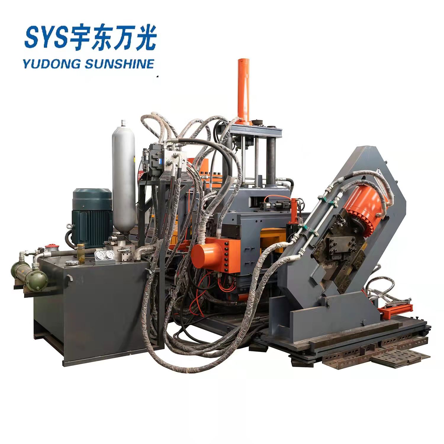
CNC channel steel Angle steel strip punching and cutting production line is mainly used for punching (round hole, long hole, special-shaped hole), printing and cutting of channel steel, Angle steel and strip steel profiles in electric power, communication, automobile, steel structure and other industries.The machine has wide processing range, high efficiency, high dimensional accuracy and simple operation.
The CNC production line punching, cutting, marking using hydraulic drive.Hydraulic system with solenoid valve reversing, simple structure, easy to use, easy to control and maintenance.The NUMERICAL control system of this numerical control production line uses the computer as the man-machine interface, the computer through the program control PLC to servo motor, cylinder, cylinder and other power components to send instructions, control it according to the set action operation, complete the processing of parts.
This NUMERICAL control production line can not only realize numerical control in channel steel web and wing plate, Angle steel wings, and longitudinal strip steel to ensure the spacing of punching holes;In the transverse use of numerical control, so as to achieve the channel steel web, Angle steel a flank plate, strip multi-alignment punching;In the vertical direction also using NUMERICAL control, can achieve channel steel wing plate, Angle steel another wing plate multi - distance punching.The shearing unit is single-edge shearing, and the clearance between upper and lower blades can be adjusted according to the material thickness by adjusting the pad blades.To sum up, the automatic production line realizes the punching, printing and shearing operations of channel steel, Angle steel and strip steel with multiple varieties and multiple holes.

1. Structure Overview
The equipment consists of six parts.They are: feeding part, feeding part, host part, finished product blanking part, electrical control part, hydraulic power part.
1) Feeding part
The feeding part is composed of the feeding platform part and the side pushing part
Material platform: by motor, reducer through sprocket, chain drive, through three long shafts, six homemade couplings to achieve the synchronization of four strip dial block chain.This makes the profile smooth and low noise in the conveying process.The function of this part is to transport strip steel and channel steel (with the opening up) to the waiting area, to be taken by the claw.
Side push material: composed of side push cylinder, control solenoid valve, side push claw and other parts, through the forward push of the cylinder will be part of the material from the chain to the material channel positioning wheel.
2. Schematic diagram of side push part:
The electrical control system of this machine is advanced and reasonable, the workpiece programming is easy to learn, and the operation is simple.
Configure the upper computer, and install special automatic programming and system control software, complete the connection of the servo motor, to ensure fast, accurate positioning and maintenance free.The control software can conveniently and flexibly manage the contents of the workpiece library and display the workpiece graphics in real time on the screen.The control software can realize automatic relocation function.The control software monitors the operation of the machine at any time. When a fault occurs, the CRT will display the detailed fault cause and treatment method.
3. Hydraulic power part
The machine adopts independent hydraulic station, easy to maintain the equipment, all the pipe joints adopt sleeve type connection, fundamentally avoid joint leakage, hydraulic valve adopts valve block connection, at the same time using plate valve and cartridge valve, reduce the pipeline connection, the hydraulic system is tighter.Line losses are minimized.System efficiency has been fully brought into play.
4. Main technical parameters of the equipment
| No. | Item | unit | specification | |
| 1 | Channel size | 8#-18# | ||
| Angle size | mm | L63X4-L140X10 | ||
| Flat bar size | mm | 60X5-180X10 | ||
| 2 | Raw material length | mm | 9000 | |
| 3 | Max. Punching diameter | mm | φ26 (web slot hole 22X60, flange slot hole) | |
| 4 | Punching force | KN | 1000 | |
| 5 | Cutting force | KN | 1500 | |
| 6 | Punching sides | side | 3 | |
| 7 | Punching head quantity of each side | piece | 4+2+2 | |
| 8 | Row of each punching side | row | arbitrarily | |
| 9 | Cnc axis | No. | 3 | |
| 10 | Min. End cutting length | mm | 50 | |
| 11 | Hydrualic force | Mpa | 25 | |
| 12 | Hydraulic cooling way | Water cooling | ||
| 13 | Pneumatic system pressure | Mpa | 0.8 | |
| 14 | Feeding speed | m/min | 90 | |
| 15 | Punching speed | min-1 | 40-50 | |
| 16 | Whole dimension | m | length | ≈22 |
| m | width | ≈4 | ||
| m | height | ≈3 | ||
| 17 | Total power | kW | ≈42 | |
| 18 | Total weight | kg | 11000 | |
| 19 | Finished work piece length | mm | 6000 | |
| 20 | Marking number | piece | 10 | |
| 21 | Marking group | group | 1 | |
5. Configuration of main components of the equipment
| No | name | brand |
| 1 | PLC | mitsubishi |
| 2 | Servo driver | Japan panasonic |
| 3 | Servo motor | Japan panasonic |
| 4 | Hydraulic station (water cooling) | China |
| 5 | Hydaulic cylinder | China |
| 6 | Ball screw | taiwan |
| 7 | Guide way | taiwan |
| 8 | main control pneumatic element | AIRTAC |
| 9 | hydraulic solenoid valve | Italy |
| 10 | Seal ring | china |
| 11 | sense switch | Labino |
| 12 | low-voltage apparatus | Schneider |
(In case of delivery time and other problems, products of other brands with the same quality can be replaced)
 English
 Русский
 Español
 العربية


