English
 Русский
 Español
 العربية
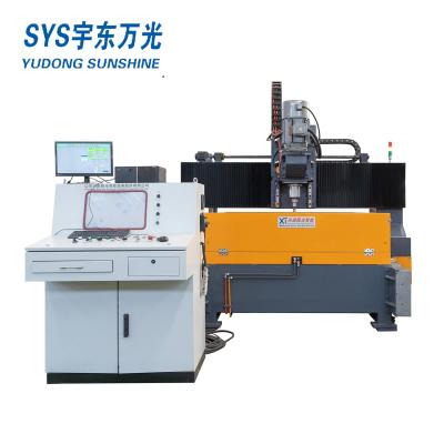
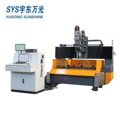
CNC H Beam Drilling Machine
The production line is mainly used in drilling and sawing of H beam, U beam which are applied in the fields, such as construction, bridge, boiler, stereo garage <offshore drilling platform and, specially, in steel structure which requires high precision and easy operation. This is machine is necessary for steel structure fabrication.
1. Structure and configuration:
The combination production line consists of YBHD1250/3 drilling line is with in feeding and out feeding conveyors ,and one CNC control device and two side conveyors, along with electrical system, hydraulic system, air cooling and lubrication.
The combination line adopts Z form arrangement that the drilling line and the band saw are installed in parallel and connected by transverse convey0r. Each of the two in feed conveyors equips a NC feeder dolly with servo motor on the datum side and side push device to push the work piece to the datum side; the drilling line equips an automatic transverse conveyor to upload work piece; the out feed conveyor equips roller to move the work piece out of the process zone and to the transverse conveyor.
In the working process, the personal should lift the work piece to the automatic transverse conveyor, after the work piece is uploaded to the in feed conveyor from the transverse conveyor, the side push moves the work piece to to the datum side, and the dolly moves the work piece to the processing zone to drill, after the drilling, the roller moves the work piece to the out feed conveyor, the transverse conveyor which connects drilling line and band saw moves the work piece from the out feed of the drilling line to the in feed of the band saw to cut the work piece, after the cutting the work piece is downloaded to the out feed, and the transverse conveyor of the band saw moves the work piece out of the processing zone.
The process sequence is from drilling to cutting, the long work piece which is meant to process into several pieces can be drilled integrally and then cut in to pieces. The transverse conveyor between two lines in Z form arrangement can can adjust the process speed. The Z form arrange let these two lines work both together and separately, when one of them is in maintaining the another line can work independently.

2. Configuration
The combination line line includes dolly, dolly track, feed conveyor, feeding line, YBHD1250 Drilling line, electrical control system, hydraulic system, air cooling system, lubrication and etc.
Terms to explain:
1. Dolly: driven by servo motor with gear box via rack and pinion, the work piece is clamped by the jaw in order to lengthwise in feed and positioning.
2. Dolly track: bear dolly to in feed, this track can by customized.
3. Feed conveyor: consist of in feed conveyor and out feed conveyor to bear and output the work piece.
4. Feeding line: this transverse line consists of four in feed frames to automatically upload work piece.
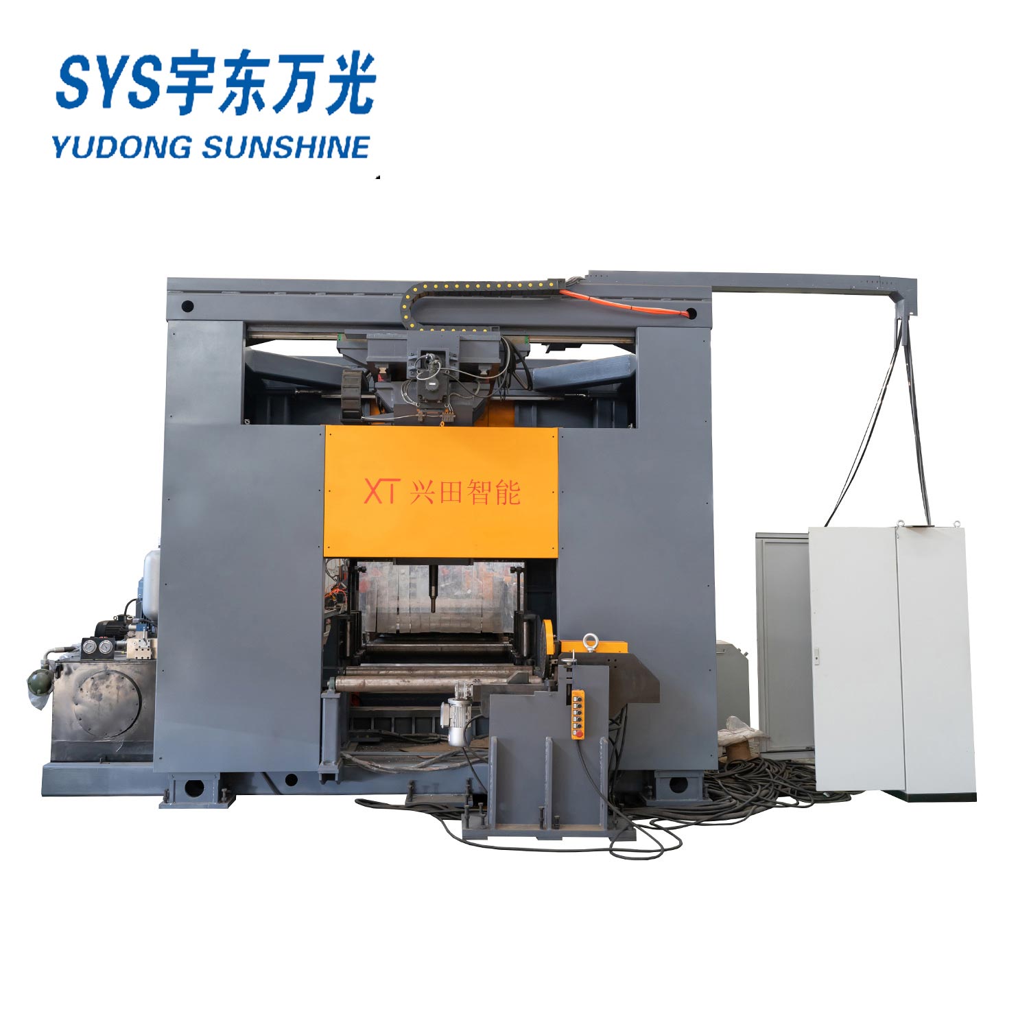
5. YBHD1250 drilling line: 3D drilling machine has three drilling heads with spindle. The side drilling head has vertical positioning, and vertical drilling head has radial positioning.
6. Equip two-pillar-closed structure, linear guide, possess high stiffness and efficiency.
7. Hydraulic system: equip with oil tank, low pressure pump set, cooler, main valve block and other control valve unit.
8. Electrical control system: with PLC and computer, two sets of it.
9. Hydraulic system: control hydraulic movements and support hydraulic power.
10. Air cooling system: adopt mist cooling for drilling line, band saw adopts water cooling.
11. Lubrication: VERSA lubricating system, support linear guide, guide screw, bearing and etc., some other parts of this line apply artificial lubricating.
1. Main Specification:
| Model | YBHD1250 | ||||
| Workpiece size | H Beam | Web x Flange (mm) | 150x80~1250x600 | ||
| U Beam | WebxFlange (mm) | 150x80~1250x400 | |||
| Box Beam | WebxFlange (mm) | 150x80~1250x400 | |||
| Angle Beam | WebxFlange (mm) | 200x200x16 | |||
| Max. Thickness(mm) | ≤80 | ||||
| Max. material length(mm) | 12000 | ||||
| Short material limiting | mm | Automatic processing≥3000 | |||
| Manual processing: 690~3000 | |||||
| Spindle | Spindle Axis | 3 | |||
| Spindle taper | BT40 | ||||
| Spindle rotation speed(r/min)Stepless speed regulation | 200~3000 | ||||
| Max. hole diameter(mm) | Fixed Side, Moving Side | 8 - 40 (Carbide and U-drill)40 - 50 (U-drill only)(High Speed) | |||
| Intermediate Unit | |||||
| Center line movement scope(mm) | Center slide table/Horizontal direction | 50~1450 | |||
| Fixed side/movement side Vertical direction | 30~770 | ||||
| 3 Positioning CNC axis moving speed | m/min | 0-10m/min | |||
| 3 feed CNC axis moving speed | m/min | 0-5m/min | |||
| Web width detection stroke | mm | 1100 | |||
| Web height detection stroke | mm | 290 | |||
| Motor power | Spindle motor power (KW) | 3*11 | |||
| Servo motor power of 3 Pcs feeding Axis(KW) | 3*2 | ||||
| Servo motor power of 3 Positioning Axis (KW) | 3*1.5 | ||||
| Feeding Trolley | Feeding trolley servo motor(KW) | 5 | |||
| Maximum feeding speed(m/min) | 20m/min | ||||
| Maximum feeding weight(Tonnes) | 10T | ||||
| Control system | CNC System | Japan YOKOGAWA PLC | |||
| CNC Axis Quantity | 7 | ||||
| Hydraulic system | Max. Hydraulic Pressure (MPa) | 7.5 | |||
| Motor power(KW) | 5.5 | ||||
| Cooling system | No. of Nozzle | 3 | |||
| Pressure of compressed air (Mpa) | ≥0.5 | ||||
| Cooling way | Internal Cooling & External Cooling | ||||
| Tool Magazine(optional) | Tool Magazine Quantity | 3 | |||
| Tools quantity for each Magazine | 4 Pieces | ||||
| Marking unit(optional) | No. of Characters | 36 Characters | |||
| Characters Size | Φ10 mm | ||||
| Imprinting Depth | 0.8~1.5mm | ||||
| Position servo motor(KW) | 0.75 | ||||
| Working environment | Working power | Three phase four wire system 380±10%V, 50HZ | |||
| Control power | 220±10%V 50HZ | ||||
| Operate power | 24V DC | ||||
| Working temperature | 0℃ ~ 40℃ | ||||
| Humidity of environment | ≤75% | ||||
| Overall dimension(LXWXH)(mm) | About 6000x2100x3400 | ||||
| Main Machine weight (Kg) | About 8000 | ||||