English
 Русский
 Español
 العربية
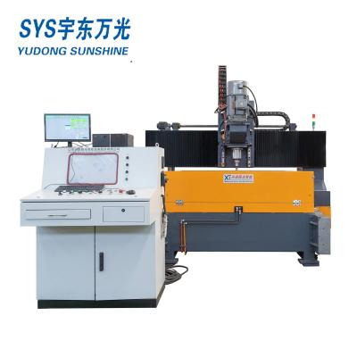
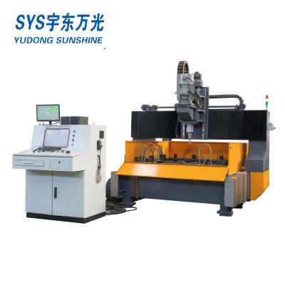
C Channel Punching Machine
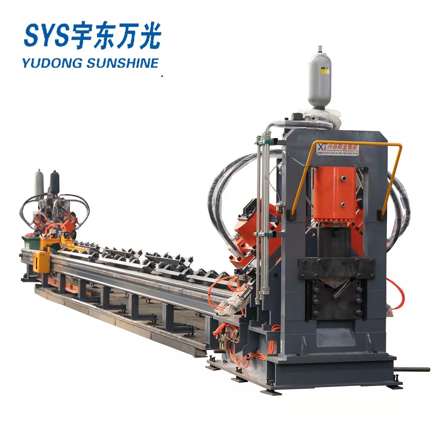
After the car clamping material to promote the material into the host first punching work position, the inner side of the host by the cylinder (SC50*200) control of the pushing material out, the material will be transverse positioning, and then, by the oil cylinder (25KN) control of the pressing material under the material pressure, punching.Side push does not return when feeding.When the clamp needs to enter the main machine, the punching unit moves laterally to give way to the clamp.At the same time punching side push back to the back position.
Feeding channel and feeding trolley these two parts are inseparable. At work, the clamping claw on the CNC car is controlled by the clamping cylinder to clamp the side pushing part of the material sent to the material, according to the feed line linear guide rail operation, promote the feed line forward into the material, the car with the fastest speed of 90 meters/minute will be sent to the host machine for marking, punching, shearing operations.Send into the car is equipped with lifting cylinder, in a material clamp rod out of the host after lifting the cylinder control clamp rod lifted with the car back, at the moment you can push the next material feeding channel positioning wheel, realize fast feeding time saving, improve work efficiency.

Main technical parameters of the equipment
| No. | Item | unit | specification | |
| 1 | Channel size | 8#-18# | ||
| Angle size | mm | L63X4-L140X10 | ||
| Flat bar size | mm | 60X5-180X10 | ||
| 2 | Raw material length | mm | 9000 | |
| 3 | Max. Punching diameter | mm | φ26(web slot hole22X60, flange slot hole) | |
| 4 | Punching force | KN | 1000 | |
| 5 | Cutting force | KN | 1500 | |
| 6 | Punching sides | side | 3 | |
| 7 | Punching head quantity of each side | piece | 4+2+2 | |
| 8 | Row of each punching side | row | arbitrarily | |
| 9 | Cnc axis | No. | 3 | |
| 10 | Min. End cutting length | mm | 50 | |
| 11 | Hydrualic force | Mpa | 25 | |
| 12 | Hydraulic cooling way | Water cooling | ||
| 13 | Pneumatic system pressure | Mpa | 0.8 | |
| 14 | Feeding speed | m/min | 90 | |
| 15 | Punching speed | min-1 | 40-50 | |
| 16 | Whole dimension | m | length | ≈22 |
| m | width | ≈4 | ||
| m | height | ≈3 | ||
| 17 | Total power | kW | ≈42 | |
| 18 | Total weight | kg | 11000 | |
| 19 | Finished work piece length | mm | 6000 | |
| 20 | Marking number | piece | 10 | |
| 21 | Marking group | group | 1 | |
Configuration of main components of the equipment
| No | name | brand |
| 1 | PLC | mitsubishi |
| 2 | Servo driver | Japan panasonic |
| 3 | Servo motor | Japan panasonic |
| 4 | Hydraulic station (water cooling) | China |
| 5 | Hydaulic cylinder | China |
| 6 | Ball screw | taiwan |
| 7 | Guide way | taiwan |
| 8 | main control pneumatic element | AIRTAC |
| 9 | hydraulic solenoid valve | Italy |
| 10 | Seal ring | china |
| 11 | sense switch | Labino |
| 12 | low-voltage apparatus | Schneider |
(In case of delivery time and other problems, products of other brands with the same quality can be replaced)